OTDR, Optical Time-Domain Reflectometer.
Why, Where How and the importance of bi-directional testing.
Reliable and accessible fibre links are the very foundation of a sound optical network. To assess the integrity of the infrastructure, we need accurate and faster methodologies and testing devices.
The Optical Time-Domain Reflectometer (OTDR) is a powerful test instrument that detects and locates problems in newly installed fibre links. It calculates fibre attenuation, uniformity, splice and connector losses, and then provides pictorial trace signatures. The OTDR is used to ensure that the cable has not been damaged during installation and that each splice is properly made, especially in a long-haul carrier cable that often include many splices.
However, it is also used for troubleshooting problems, such as finding locations of cable breaks. For premises cabling that usually has short cable runs and often does not include splices, the OTDR is poised as an alternative to insertion-loss testing with a light source and power meter. The successful use of an OTDR requires knowing how to operate the instrument, choosing the proper measurement parameters, and correctly interpreting the traces.
OTDR is a powerful test instruments for fibre optic cable testing: when used properly, it not only simplifies testing requirements, but also helps to increase the reliability and value of the network.
Its purpose is to detect, locate, and measure elements at any location on a fibre optic link.
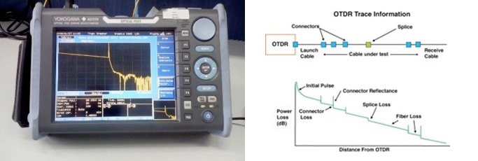
The OTDR works like radar—sending pulses down the fibre and looks for a return signal, creating a display called a “trace” or “signature” from the measurement of the fibre. Simply by connecting one end of the fibre, OTDR can calculate fibre attenuation, uniformity, splice, and connector losses, then provides pictorial trace signatures (a graph of optical power in dB versus the length of the fibre). Its ability to locate and measure reflectance and loss makes OTDR the troubleshooting and fault locating equipment of choice.
There seem to be a lot of confusion about where and how to properly use an OTDR. Given the two distinctly different fibre optic applications—
- Outside plant as in Carrier networks NBN and Telstra etc
- Indoor or campus cabling as in premises cabling.
The functions of OTDR varies in different situations:
- In a long outside-plant cable with many splices, the OTDR is indispensable and often used to ensure the cable has not been damaged during installation and that each splice is properly made. And it is used for troubleshooting problems, such as finding locations of cable breaks.
- Premises cabling has short cable runs and often does not include splices, so the OTDR is poised as an alternative to insertion-loss testing with a light source and power meter— (The OTDR priced roughly 10 times higher than the LS&PM.
How to use an OTDR for Fibre Testing?
OTDR testing can either use one launch cable for testing or use a launch cable together with a receive cable.
Use a launch cable with the OTDR when testing so the high-power test pulse of the OTDR cannot overload the instrument’s receiver. Without the launch cable the OTDR will be blind at this point of time.
The OTDR requires some time for recovery, which causes OTDR dead zone. In general, there are two types of dead zones—event dead zone (EDZ) and attenuation dead zone (ADZ).
The Event dead zone: the minimum distance between the beginning of one reflective event and the point where a consecutive reflective event can be detected.
Event dead zone is the location where the falling edge of the first reflection is 1.5 dB down from the top of the first reflection.
The Attenuation dead zone: the minimum distance after which a consecutive non-reflective event being detected and measured. It is the location where the signal is within 0.5 dB above or below the back-scatter line that follows the first pulse.
The attenuation dead zone specification is always larger than that of a event dead zone.
Dead zones can be overcome by connecting a long launch cable to the OTDR.
Launch cable fibres place a necessary length of fibre between the OTDR and the actual fibre being measured, providing both the time and distance required for the OTDR to effectively measure the characteristics of the fibre being tested. Launch fibres do not interfere with the actual fibre, so they are very secure for identifying faults in the total length of fibre.
OTDR testing with launch cable or OTDR Testing with Launch and Receive Cable.
Launch and receive cables consist of spools of fibre with specific distances. They are usually connected to both ends of the fibre being tested, to qualify the front end and the far end connectors using an OTDR.
The length of the launch and receive cables depends on the link being tested—generally between 300 m and 500 m for multimode testing and between 1000 m and 2000 m for single-mode testing. For carrier network very long haul, 4000 m of cable may be used.
The larger the pulse width, the longer the launch cable and receive cables. Always note, that launch and receive cables must be the same type as the fibre under test. OTDR testing with launch and receive cable OTDR Parameter Setup:
The successful use of an OTDR requires knowing how to operate the instrument, choosing the appropriate measurement parameters, and correctly interpreting the traces.
Setting up the instrument; the key element in making good OTDR measurements is the correct set up.
OTDR test range: the first OTDR parameter to set is the range, which is the distance the OTDR will measure. The range should be at least twice the length of the cable that you are testing.
Longer ranges will make the resolution of the trace poorer, and shorter ranges may create distortions in the trace.
OTDR test pulse width: set up the OTDR test pulse width to the shortest pulse width available, which will provide the highest resolution, giving the best “picture” of the fibre being tested.
This is usually listed in nanoseconds (ns), with typical choices of 10 to 30 ns.
OTDR test pulse width wavelength: Normally, it is 850 nm on multimode fibre optic cable and 1,310 nm on single-mode (customer) —the shorter wavelength has more back-scatter, so the trace will be less noisy. After initial tests, you can make measurements at the longer wavelengths (1,300 nm on multimode and 1,550 nm on single-mode) and compare traces at the two wavelengths.
Number of averages for each trace: To improve the signal-to-noise ratio of the trace, the OTDR can average multiple measurements, but the more averaging, the more time it takes. Usually, 16 to 64 averages are adequate.
The conclusion is that the OTDR is an invaluable test instrument, that can locate problems and faults in your optical fibre links, ensuring a reliable and sound network performance.
Once the operator is familiar with OTDR function and how to use it properly, they are prepared to detect and eliminate optical fibre events.
Reading and analysing the trace.
Reflectance and backscatter are measured in dB, and the horizontal axis represents distance.
The X axis measures distance, and the Y axis measures attenuation and reflection in dB.
It is important to identify the three troublesome events:
- Ghosts
- Nonreflective breaks.
- Gainers*
To avoid confusion, it is important to know the lengths of all the fibres on the network.
Guide to benchmark measurements:
<0.05dB for single-mode long-distance and short links for splice, <0.5dB for single-mode long-distance and short links for mated connector, >-40dB for single-mode reflectance, and 0.40dB/km at 1310nm, 0.25dB/km at 1550nm for single-mode long-distance and short links for attenuation.
These figures do vary slightly, depending on network owner, cable manufacturer and relevant specifications.
* Masking or distorting effect is also known as a gainer, since the amount of observed backscattering will be higher after the loss event than before it. Conversely, if the transition is from a higher backscatter coefficient segment to a lower one, the resulting signature might incorrectly show a higher loss event at this same location.
Using an OTDR
Introduction to the OTDR;
An Optical Time Domain Reflectometer (OTDR) is a specialised device that is used to measure the quality of an optical fibre link. It works by sending a pulse of light down the fibre and measuring the time and intensity of the light that is reflected back. This information can then be used to determine the length and attenuation of the fiber, as well as to identify any faults or breaks in the fibre.
Generic step-by-step instructions for using an OTDR:
1 A. Read the instructions for the particular brand and model that you are using.
B. Allow 15 minutes warm up and settling of the OTDR
C. No less than 30% battery charge.
2. Turn on the OTDR: Press the power button to turn on the OTDR. Wait for it to complete the boot-up process, which may take a few seconds. See above.
3. Connect the OTDR to the fibre: Use a fibre connector to connect the OTDR to one end of the fibre you want to test. Make sure the connection is secure and tight.
4. Set the measurement parameters: Using the OTDR’s user interface.
5. Set the measurement parameters according to the specifications of the fibre you are testing. This includes the pulse width, wavelength, and measurement range.
6. Launch the test: Press the “Start” button on the OTDR to begin the test. The OTDR will send a pulse of light down the fiber and measure the time and intensity of the light that is reflected back.
7. Analyse the results: After the test is complete, the OTDR will display a graph of the measured data. Use the software provided by the OTDR to analyse the graph and identify any faults or breaks in the fibre. This may include analysing the shape of the trace, the distance between the events, the magnitude of the events, and the attenuation of the fibre
8. Repeat the test: If necessary, repeat the test from the other end of the fibre to ensure that the results are consistent.
This is recommended, at least two frequencies bi-directional.
9. Save the results: Save the results of the test for future reference. Many OTDRs will allow you to export the data to a file for analysis using external software.
10. Disconnect the OTDR: When you are finished testing the fibre, disconnect the OTDR from the fibre and turn it off.
Note that the instructions are general and may vary depending on the specific model and manufacturer of the OTDR you are using. Always consult the user manual for your specific OTDR to ensure you are following the correct procedures.
Recommended pulse widths and wave lengths.
The pulse width and wavelength settings for an OTDR depend on the characteristics of the fibre being tested, rather than the length of the fibre run.
The length of the fibre can affect the range and resolution of the OTDR measurement.
General guidelines, pulse width and wavelength settings based on the type of fibre being tested:
Single-mode fibre:
- For short runs (less than 1 km), use a pulse width of 5-10 ns and a wavelength of 1310 nm.
- For longer runs (more than 1 km), use a pulse width of 10-30 ns and a wavelength of 1550 nm.
Multimode fibre:
- For short runs (less than 1 km), use a pulse width of 30-50 ns and a wavelength of 850 nm.
- For longer runs (more than 1 km), use a pulse width of 500-1000 ns and a wavelength of 1300 nm.
Why and how of bi-directional testing with OTDR.
Cross reference with the specifications and information for testing as contained in the AS11801.
What is Bi-directional is OTDR Testing?
An benefit of OTDR testing is that it requires access to only one end of the fibre optic cable to perform. Because the distance and attenuation measurements are based on optical light backscattering and Fresnel reflection principles, scattered and reflection can be analysed at the same location where the test signal originates.
To minimise the impact of errors and uncertainty that can accompany conventional unidirectional testing, bi-directional OTDR testing methods have been developed to enhance the accuracy and precision of this important test methodology.
As the name implies, bi-directional OTDR testing is a method of optical fibre characterisation and loss testing that is performed from both ends of the fibre run. How a Bi-directional Test Works In addition to the OTDR equipment and fiber optic cable under test, a basic OTDR test configuration also includes a launch cable and a receive cable.
The launch cable connects the OTDR test port to the fibre run under test and is referred to as a “pulse suppressor”, since it serves to stabilize the initial light pulse from the OTDR before it enters the tested cable.
The receive cable connects at the far end of the run and provides a mated fibre connection/junction, with an appropriate run-out segment, allowing the losses of the terminating connector to be assessed. The existence of these launch and receive cables creates a symmetrical configuration at both ends of the run.
In bi-directional OTDR testing, the same fibre characteristics are measured again, using the same (or an additional) OTDR at the opposite end of the run and averaging or combining the results with those obtained in the initial direction. Bi-directional fibre testing can often produce more accurate results than unidirectional testing, based on the test methodology itself. Since Rayleigh backscattering is used to quantify attenuation and signal loss events, the backscatter coefficient of the fibre must be known and programmed into the OTDR.
These coefficients may vary from fibre to fibre, or even within a single fibre. The resulting effect can be misinterpreted as excess signal attenuation or even negative attenuation (gain) at junctions between sections in a fibre run. This variation can be compensated for by averaging the results for end-to-end loss and individual loss at each connection or splice, using a bi-directional OTDR test. Benefits of Bi-directional OTDR Testing If the transition at a fibre junction result in a fibre with a lower backscatter coefficient transitioning to a fibre with higher coefficient, the result could be a masking of the actual loss at the interface or splice.
This masking or distorting effect is also known as a gainer since the amount of observed backscattering will be higher after the loss event than before it. Conversely, if the transition is from a higher backscatter coefficient segment to a lower one, the resulting signature might incorrectly show a higher loss event at this same location.
Averaging the values obtained from opposite ends can provide a more accurate quantification of loss.
Another benefit of bi-directional optical fibre testing is the mitigation of dead zones, where the initial Fresnel reflection from an event, such as a splice or connector, has temporarily blinded the OTDR detector rendering it unable to see reflections and backscatter from additional events directly behind the splice or connector.
Since the effect of dead zones tend to occur more frequently closer to the OTDR, measuring again from the opposite direction will allow an accurate assessment for the portion of cable that was included/masked in a dead zone during the first measurement.
Long-haul carrier fibre optic cable runs, networks between cities and towns, state to state etc, require powerful OTDRs with a higher dynamic range to accurately assess the fibre span uni-directionally.
Using bi-directional fibre test is an excellent way to improve the test integrity over these very long distances. By combining OTDR measurements obtained from each end, the impact of test pulse degradation at the farthest points from each OTDR can be minimised.
Despite the advantages in accuracy and range to be gained through bi-directional OTDR testing, the additional complexity that can accompany this method needs to be considered. In a basic bi-directional test configuration using a single OTDR device, the OTDR must be transported from one end of the fibre run to the other to complete the testing. Even when duplicate OTDRs are utilised, bi-directional testing can add additional set-up time, transportation costs and analysis to the OTDR test process.
Test instruments positioned at either end of the fibre run can communicate and share data nearly instantaneously via Ethernet, WiFi or mobile hotspots. These devices also include on-board report generation for convenience and speed.
There are standards and specifications for unidirectional and bi-directional testing contained in the AS 11801
In summary:
Bi-directional OTDR testing of fibre optic cable runs and links gives a far more accurate picture of the network. High lighting possible hot spots that a LS&PM loss test is not designed to do.
The method uses the same OTDR equipment and fibre optic cables, as well as a launch and receive cables, to create a symmetrical configuration seen from both ends of the run.
Bi-directional OTDR testing can minimize the impact of errors and uncertainty, compensating for variations in backscatter coefficients between different fibres or within a single fibre. This method can also mitigate dead zones and provide accurate assessments for long-haul runs.